07 — Process skid systems

Vapour Recovery Unit (VRU) LNS-VRU

Recover valuable hydrocarbons. Reduce VOC emissions. Improve terminal safety.

01 — Product overview

Hydrocarbon vapour control for tank farms, loading terminals & distribution facilities

The LINESIG Vapour Recovery Unit (VRU) is an engineered industrial system for collecting and treating fuel vapours displaced from road tanker, railcar, marine loading and storage operations. It is designed to reduce uncontrolled volatile organic compound (VOC) emissions while enabling recovery of reusable hydrocarbon product where technically and economically feasible.

LINESIG vapour recovery systems are engineered to capture and recover volatile hydrocarbon vapours released during fuel storage, transfer and loading operations. The systems can combine vapour collection, conditioning, adsorption or condensation, vapour recovery and automated controls in a packaged solution tailored to fuel properties, operating cycles and required emission limits.

For multi-tanker gantry systems, vapour from individual loading bays is routed through a common vapour-return header to a centralized recovery package, allowing the VRU to operate as an integrated part of the loading rack with batch, ESD and terminal automation interfaces.
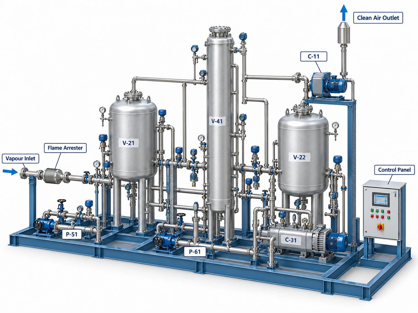
LineSig Vapour Recovery Unit (VRU) at a tanker loading terminal

Typical vapours / service media

Gasoline / motor spirit vapours; light petroleum and hydrocarbon solvent vapours; naphtha and compatible volatile liquid vapours; other VOC-bearing streams subject to compatibility assessment. Diesel, kerosene, jet fuel and heavier products may produce lower vapour loads, but applicability and recoverability must be confirmed for the operating conditions.

Important: VRU suitability depends on vapour composition, water content, oxygen content, contamination, temperature and flammability limits. Highly reactive, corrosive, polymerizing or incompatible streams require special engineering.

02 — Product range

Technology options

Activated Carbon Adsorption VRU

Vapours pass through engineered activated-carbon beds. Depending on the selected design, the saturated bed is regenerated using a vacuum or other approved cycle, followed by recovery of the desorbed hydrocarbons.

Condensation VRU

Vapours are cooled under controlled conditions to condense recoverable hydrocarbon fractions. Cooling stages and any polishing step are selected for the actual vapour mixture.

Hybrid / Multi-Stage VRU

A tailored combination of adsorption, condensation or other separation technology where the required capture performance and operating profile justify a hybrid arrangement.

Selection of the final technology, capacity and performance guarantees requires a project-specific engineering study.

03 — Benefits

Key benefits

  • Reduces hydrocarbon VOC releases from suitable loading and transfer operations
  • Recovers valuable hydrocarbon fractions for potential return to an approved product system
  • Helps facilities pursue applicable emission-control and environmental objectives
  • Skid-mounted or modular construction to suit brownfield and new-build sites
  • Engineered for variable vapour flow, loading cycles and product composition
  • Integrated vapour handling, instrumentation and automatic control
  • Optional continuous monitoring, data logging and remote SCADA connectivity
  • Safety functions selected for flammable-vapour service and classified areas
  • Configurable for single-product or compatible multi-product duties
  • Designed for maintenance access and lifecycle serviceability

04 — Process

How it works

  1. Vapour CollectionVapours displaced during loading or tank operations are routed through a dedicated, appropriately safeguarded vapour header.
  2. Inlet Protection & ConditioningKnock-out vessels, filtration and condensate separation protect downstream equipment; additional conditioning is fitted where required.
  3. Controlled Vapour TransferA blower or other vapour-moving arrangement manages process flow and pressure within approved operating limits.
  4. Hydrocarbon SeparationActivated carbon adsorption, condensation or a hybrid process removes recoverable VOCs from the vapour stream.
  5. Product RecoveryRecovered liquid is transferred through a controlled return path to an approved collection tank or compatible process system.
  6. Treated Gas OutletTreated gas passes through the specified discharge or recirculation arrangement, with emission monitoring where required.
  7. Automatic SequencingPLC/HMI manages process steps, interlocks, alarms, standby changes and recovery cycles where applicable.

05 — Scope of supply

Main system components

  • Vapour collection header and inlet isolation arrangements
  • Inlet knock-out drum / liquid separator and filters
  • Flame/detonation protection devices where required by safety assessment
  • Vapour blower, vacuum pump or compressor as selected
  • Activated-carbon vessels and regeneration circuit where applicable
  • Condensers, refrigeration package or heat exchangers where applicable
  • Recovered-product receiver, pumps and transfer connections
  • Pressure, temperature, flow and level instruments
  • VOC / hydrocarbon / oxygen gas measurement where specified
  • Piping, automated valves, drains and appropriate relief provisions
  • Skid base, access platforms, drip trays and weather protection
  • Electrical distribution, PLC/HMI and integration interfaces

06 — Technical specification

Typical technical features

ParameterEngineering basis / available arrangement
System configurationPackaged skid, modular or site-built
Process technologyAdsorption, condensation or integrated hybrid
CapacityDesigned to project vapour flow and loading profile
Hydrocarbon recoveryDuty-dependent; no blanket recovery guarantee
Vapour inlet pressureSelected to site header and vessel design constraints
Operating modeAutomatic; intermittent or continuous duty as engineered
Vapour compositionProject-specific and verified against material compatibility
Mechanical constructionCarbon steel / stainless steel / specified corrosion-resistant materials
Area classificationElectrical and instruments selected to applicable hazardous area assessment
Process monitoringPressure, temperature, flow, level, alarm and selected emission signals
Control systemPLC/HMI with optional SCADA/DCS interface
InstallationIndoor/outdoor subject to ventilation and safety design

Typical construction / material options

ComponentMaterial / configuration direction
Vapour piping and vesselsCoated carbon steel or stainless steel per duty
Carbon adsorption bedsVessel and activated carbon grade selected for hydrocarbon mix
Seals / gasketsHydrocarbon-compatible elastomer/PTFE solutions
Condensate equipmentCS / SS construction by fluid and corrosion considerations
Skid / supportsPainted CS or SS as specified
Electrical enclosureIndustrial / hazardous-area-rated as required
InstrumentationSuitable metallurgy and process wetted materials

Available configurations

Carbon Adsorption & Regeneration

Dual-bed or multiple-bed arrangements, where appropriate, allowing adsorption and regeneration sequencing.

Refrigerated Condensation

Cooling-based recovery for suitable vapour composition and design temperatures.

Hybrid Recovery

Selected combination of recovery stages for difficult compositions or stringent discharge objectives.

Single-Point or Multi-Point Vapour Collection

Engineered vapour headers from loading lanes or other approved sources.

Integrated Terminal Automation

Communication with loading permissives, terminal monitoring and shutdown philosophy.

07 — Where it's used

Industries & applications

Petroleum Bulk Storage Terminals

Road tanker and railcar loading gantries; fuel transfer operations and vapour collection headers.

Marine Oil & Product Terminals

Vapour control from suitable vessel loading systems, subject to marine safety and interface requirements.

Refineries & Petrochemical Facilities

Selected tank vents, blending, loading and intermediate hydrocarbon transfer duties.

Fuel Distribution Depots

Gasoline and light-product truck loading and dispatch operations.

Chemical & Solvent Handling

Compatible VOC-rich vapours from filling, packaging and bulk transfer operations.

08 — Control & safety

Control & automation

  • PLC/HMI automatic operation, start-up and controlled shutdown
  • Vapour header pressure supervision and permissive interlocks
  • Vapour flow monitoring and capacity control
  • Adsorption bed sequencing / regeneration logic where applicable
  • Condenser/refrigeration sequencing where applicable
  • Product receiver level and recovery pump control
  • Filter / vessel differential-pressure monitoring where specified
  • Hydrocarbon gas / oxygen monitoring where justified by HAZOP
  • Fire and gas / emergency shutdown interface where specified
  • Event logging, alarm history and maintenance diagnostics
  • Remote status, trend data and optional SCADA/DCS communication

Safety & environmental engineering

Each installation requires a documented process safety basis, including vapour composition, explosive atmosphere and ignition source assessment, maximum permissible pressure/vacuum, overfill/condensate handling, flame propagation protection, grounding/bonding, safe discharge routing and interface with terminal ESD systems. Relief, interlock and protective-device selection shall follow the relevant project hazard assessment and applicable codes. Emission compliance is established against the approved design case and measured performance, not inferred solely from installation of a VRU.

Available options

Redundant vapour-handling trains, standby instruments, continuous outlet VOC monitoring, hydrocarbon and oxygen analyzers, integrated flame-protection arrangements, nitrogen purging, remote communications, weatherproof enclosures, preassembled modular skids, remote service diagnostics and maintenance packages — subject to engineering validation and project requirements.

09 — Ordering information

Information required for VRU selection

  • Product or solvent list, vapour composition and expected contaminants
  • Loading rates, simultaneous loading points and operating schedule
  • Minimum, normal and maximum vapour flow rates
  • Inlet pressure, temperature and humidity range
  • Target VOC outlet limit / recovery objective and testing basis
  • Available utilities: electrical, cooling medium, instrument air, nitrogen
  • Destination and specification for recovered liquid
  • Hazardous-area classification, applicable codes and site requirements
  • Footprint, access and weather / ambient requirements
  • Customer controls, documentation and FAT/SAT requirements

10 — Downloads

Documents

The documents below cover the LNS-VRU-WET reference configuration. Other technology options are engineered per project.